Popis
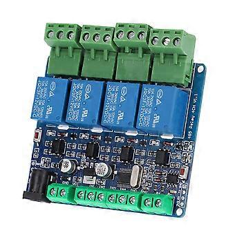
1、This is a 4‑channel 12V relay output board module. easy and convenient to install 2、High quality material can make sure the durability and stability of the product 3、The module has low power consumption, high accuracy, suitable for RS485 / TTL communication 4、Adopted of high quality electronic components, and accuracy process, ensure for the durability 5、The connecting part has good contact performance, ensure stable working
Item Type: 4-Channel Relay Module
Relay Communication: Multi-unit network 485 communication, the default communication address is 1, and the user can modify the address by himself
Note: IN1-IN4 are used to connect to the switch and read the switch status through 485, not to control the relay output through the input.
The switch status of IN1-IN4 needs to be read by the computer every time it is inquired, and data cannot be sent to 485 actively.
Note: IN1-IN4 cannot be connected to 220V (some buyers will make this mistake)
The Wiring Method is as Follows:
IN1-GND (default is high level, low level after the switch is turned on) The computer sends instructions to read the switch status.
IN2-GND (default is high level, low level after the switch is turned on) the computer sends instructions to read the switch status.
IN3-GND (default is high level, low level after the switch is turned on) the computer sends instructions to read the switch status.
IN4-GND (default is high level, low level after the switch is turned on) the computer sends instructions to read the switch status.
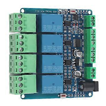
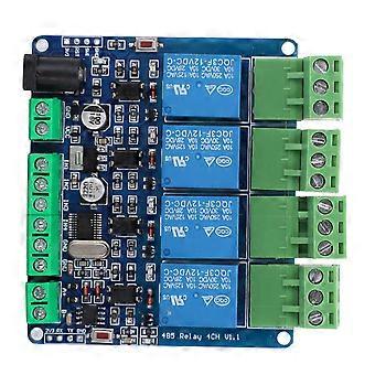
Board Resources:
1. S1 reset button
2. D5 running LED indicator
Control instruction into group sharing download
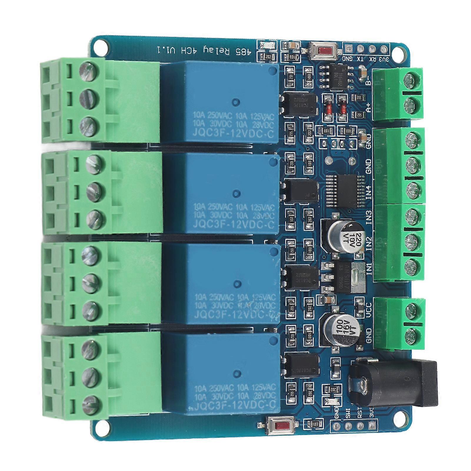
1. 4 relay outputs (one normally open, one normally closed)
2. STM8S103F3 MCU
3. 4 optocoupler isolation relay output
4. 4 relay closed LED indicators
5. Circular DC interface, and terminal DC interface. Convenient power connection (power supply voltage 5V or 12V depends on the voltage of the relay)
6. 4 input interfaces (dry node input, passive input, connected to GND)
7. One RS485 communication interface.
8. A power indicator
9. One user LED light
10. Reset button
11. A SWIM download interface-(STLINK-V2 download program, users can develop the program twice)
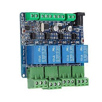
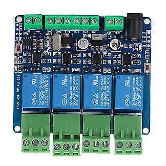
1. Connect LED to user LED
2. TX RX connects to port 485 and pin header TTL port
3. KEY user button (red button on the left)
4. EN 485 use end
5. IN1 -IN4 input ports are directly connected to the terminals
6.K1 -K4 relay output control
7. SWIM programming program J13 Size: Approx. 76 x 67mm / 3 x 2.6in
1 x 4-Channel Relay Module
-
Fruugo ID:
388901835-834014243
-
EAN:
680141788793
Informácie o bezpečnosti produktu
Prečítajte si informácie o bezpečnosti produktu špecifické pre tento produkt uvedené nižšie
Nasledujúce informácie poskytuje nezávislý maloobchodný predajca tretej strany, ktorý predáva tento produkt.
Bezpečnostné štítky produktu

Bezpečnostné upozornenia:
-
Not suitable for children under 36 months
-
Choking Hazard
-
Adult supervision recommended
Dodanie a vrátenie
Odoslané do 2 dní
Doručenie od Čína.
Snažíme sa, aby sme výrobky, ktoré si objednáte, doručili celkom v súlade s vašou špecifikáciou. Ak by ste však dostali neúplnú objednávku alebo iný tovar ako ten, ktorý ste si objednali, alebo existuje nejaký iný dôvod, prečo nie ste s objednávkou spokojní, môžete objednávku alebo niektoré produkty z nej vrátiť a za tovar dostať plnú náhradu. Pozrite si všetky pravidlá vrátenia